So, you want to install a bed probe to make leveling easier. Here are a few things you should know first:
- It will not magically solve your adhesion and bed leveling issues, you should first learn how to manually bed level
- It is not something any beginer can do and requires some understanding of the components of your printer as you need to know where to connect the probe and some tools
- It is very easy to screw something up if you are not careful, like the ribbon cable that goes to the extruder or even the probe itself if you don’t connect it properly
- A firmware update for the mainboard is required and that means you have to open up the base of your printer
- If you have a Sidewinder you will lose the extruder LED functionality
- It will put more stress on the CPU of the mainboard as it has to calculate the Z-axis position all the time while moving and will put more stress on the Z-axis drivers and motors as Z axis has to constantly move to compensate for the bed not being leveled or warped
- You will still have to mess around with the Z-offset when changing nozzle temperatures and materials
If there are so many downsides, what is it good for then ? I’m glad you asked (or didn’t):
- If you, like me, have multiple flex sheets of various heights that you change around in between prints and materials (for instance PEI for PLA and PETG, BuildTak for Nylon, etc.)
- If your bed is really warped in the middle (lower or higher) and you have no other means to get it straight
- If you like to tinker with your printer
- If you have a 32bit board and you want to put it to work, cause well… it can handle it
- If you are better at doing mods than leveling your bed
Read more about Automatic Bed Leveling (ABL) on Marlin Firmware’s website
Requirements and overview
Now that we got the pros and cons out of the way you will require the following:
- A BLTouch (or clone) probe
- The printed mount
- Longer M3 screws (M3x20) to fix the mount under the part cooling fan
- The allen keys supplied with your printer
Here are the general steps involved in the installation process:
- Print the required BLTouch mount
- Assemble the BLTouch on the mount, put the mount on the extruder and connect the cable to it (this is a bit different between the Sidewinder and the Genius)
- Update your mainboard and TFT firmware
- Calibrate your Z-offset
The BLTouch mount
So, let’s get started. First thing you need to do is to print the mount so download Waggster Mod BLTouch Artillery sidewinder X1 and don’t worry if you have a Genius the mount fits the same. As it will be part of the extruder I recommend printing it in PETG as PLA could deform from the heat, but it’s not a must.
While waiting for the mount to print watch the video tutorial on how to install. Make sure you watch it a couple of times to understand the whole process.
Steve Wagg has an excelent tutorial on installing BLTouch - Waggster Mod on a Artillery Sidewinder X1 3D Printer.
The Genius already has a plug on the extruder (behind the blue cover) so you don’t have to reuse the LED pins, but you have to be careful how you connect them.
Mount and connect
Steve’s video does a great job of explaining how to fix your BLTouch on the printed mount and then to the extruder so I’m not going to go over that again. It also explains how to connect it on the Artillery Sidewinder, not going over that either. I will explain a bit about what the connections on the BLTouch do from the diagram picture below:
1- Endstop trigger (goes to Z-min or Z-max pin)2- Ground3- Communication with the probe (goes to a servo port)4- +5V5- Ground
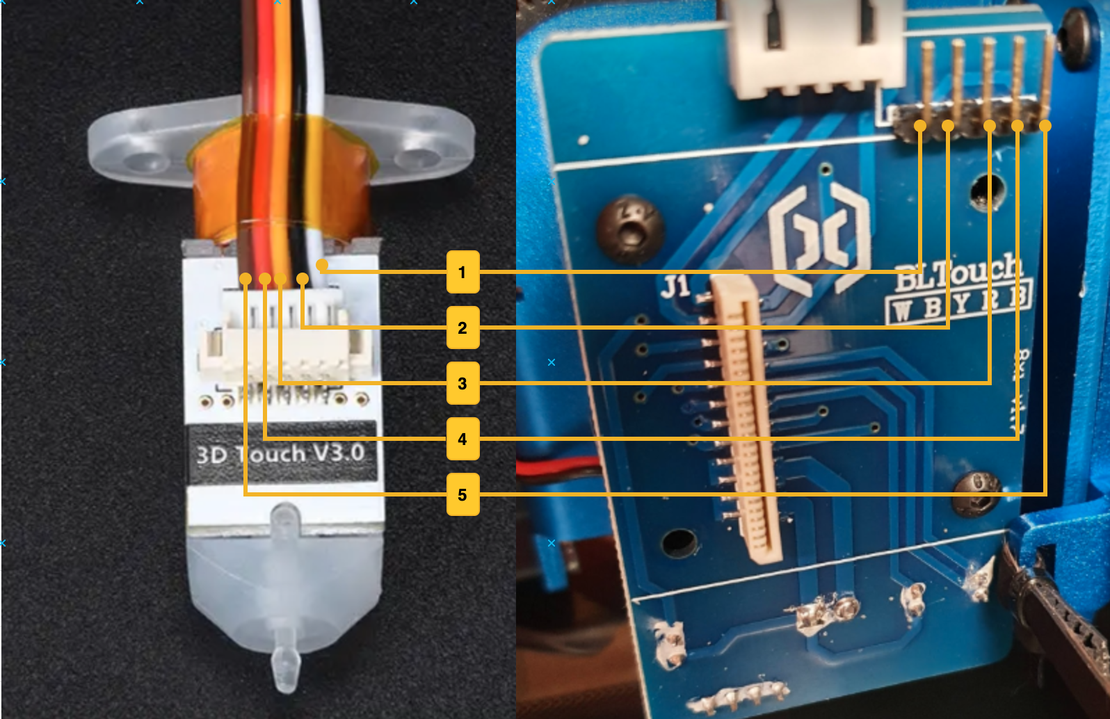
One thing you have to be careful about on the Artillery Genius is how you connect the probe wires to the plug on the extruder. Pinout is explained in the Artillery Genius ABL Port PDF provided by Artillery. Your probe has 5 wires usually grouped into 2 connectors, one with 2 wires (normally black and white) and another one with 3 wires. The order of the wires in the plug on the extruder board has to be the same as the order of the small plug that goes on the back of your probe. For some reason on my 3D Touch clone wires number 4 and 5 were reversed in the connector so I had to switch them.
Update the firmware
While the order of the updates does not really matter, everyone out there seems to start with updating the mainboard firmware first and then move to the TFT, so I will do the same.
Mainboard
If you watched the video above it should be clear how to update your mainboard firmware (open the base of your printer, disconnect the TFT cable, connect your printer to a PC and use PrusaSlicer to perform the update). Let’s go over a few thing you might run into.
Your PC might not ‘see’ the connected printer’s serial port. Make sure you don’t have any other software that might automatically grab serial ports (like Cura for instance), and if that’s not the case you need to install the CH341 serial driver. Make sure you reboot after if you’re using Windows.
One thing you might be confused about is what firmware to choose. I have highlighted the most important ones in my Upgrades - Firmware options but there are really only 2 options to choose from:
- Steve’s Firmware based on Marlin 2.x, not always up to date on the latest Marlin
- Genius Firmware based on Artillery’s Marlin 1.x that I habe built myself and used on my Artillery Genius (sorry Sidewinder owners, don’t have a build for you, but you can easily make your own just by editing the bed size and building it)
I prefer running Marlin 1.x on the default 8bit board as 2.x does not bring anything new to the table.
Whichever one you choose, they should work the same.
TFT
Updating the TFT is easy, just copy the required files on the root of your SD Card, plug it in and reboot.
While is not required to update the TFT firmware, it does make it easier to calibrate your Z-offset from the TFT rather than using something like Pronterface on the PC as it adds the comands to move the Z up and down.
As for the firmware itself, you can use the one included in Steve’s firmware or as an alternative I have also prepared a selection of my own that can be downloaded from Github. You can also build your own as it’s just a matter of editing the mks_config.txt file and adding some icons to associate with your new commands.
Calibrate the Z-offset
Altho explained in Steve’s video it might be confusing for beginers when setting up a probe to understand what the Z-Offset is and how to choose the apropiate value. The probe (a BLTouch clone in our example) has a pin that retracts when touches the bed and triggers a signal similar to an endstop. That is what the printer thinks is the zero point on the Z axis (remember how the printer only knows where it is based on a reference point ?).
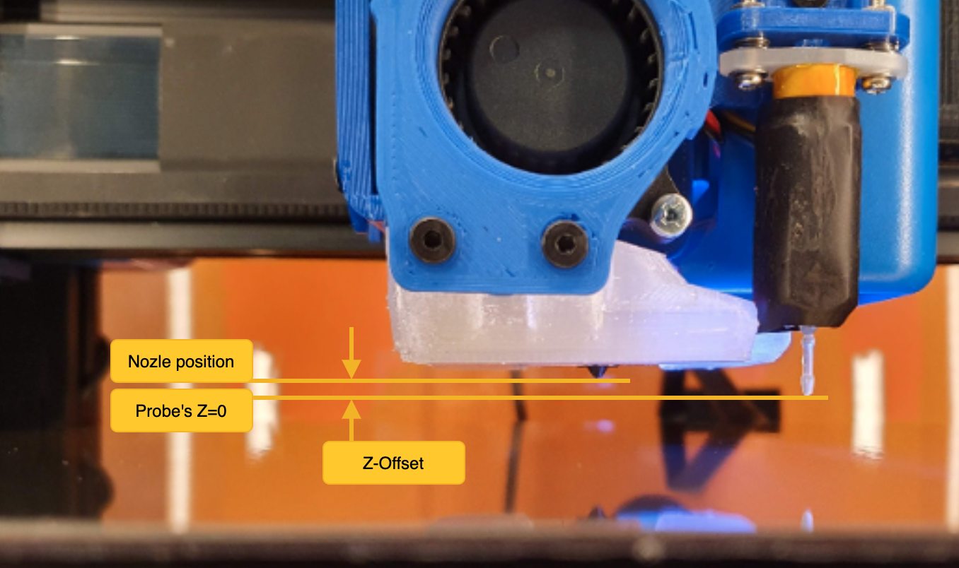
The distance between the probe’s trigger point and the actual position of the nozzle is the Z-Offset. It is always a negative number as it needs to lower the nozzle, basically substracting that value from the coordinates in your G-code file. For example if you have a Z-offset of -1.5 and you want to move your nozzle to print the first layer at 0.2mm, you would issue the command to move at Z = 0.2 but the printer will actually move at Z = 0.2 - 1.5 = -1.3.
As you saw in Steve’s video, you need to make your initial adjustment while heated to your preffered temperature (I recommend using 210C since it’s most common for PLA) using the TFT commands and then save the new Z-Offset to EEPROM. This makes it easier than guessing it. But it might still not be enough and you would need to adjust it manually especially when changing printing temperatures, just like you would with regular bed leveling because the whole heatblock expands and that will make the Z-offset smaller if you increase the temperature or bigger if you decrease it from the reference temperature you initially calibrated at. To view your current Z-Offset you can use any terminal (like Pronterface or OctoPrint’s terminal), issue an M503 and look for the Z-Probe Offset M851.
Send: M503
...
Recv: echo:; Z-Probe Offset (mm):
Recv: echo:  M851 X28.00 Y-33.00 Z-1.50
Based on my experience I noticed that there is a difference of more or less 0.0035mm for each 1C of temperature difference. So for example if you calibrated at 210C and you want to print something at 240C, you have a difference of 30C so that would mean you have to add 30 * 0.0035 = 0.105 to your Z-Offset making it -1.5 + 0.105 = -1.395 or rounded -1.39 or -1.40. While it won’t make much of a difference for +/-10C you can see that for 30C it’s half a layer size of 0.2mm and that will count. Of course your results might vary depending on your nozzle and heatblock materials if you upgraded from the original ones, and also some materials preffer to be closer to the bed while others a bit further away, so feel free to experiment with the offset.
To set a new offset you can use M851 Z-1.70 (replace -1.70 with the new offset of course). You can put that in your startup G-code for the filament for Prusa Slicer or use a plugin like Z Offset Setting in Ultimaker Cura.
Getting the right Z-offset might take some time at first but once you do it a few times you will get the hang of it just like with the manual bed leveling.
Slicer changes
For the Auto Bed Leveling (ABL) to work, you also need to make some changes to your slicer’s startup G-code script. To perform the measurements first the printer needs to be homed with G28 and then ABL need to performe the probing using G29. But before all this, you need to preheat the bed as it will expand a bit when heated.
You can check out my startup G-code presets for PrusaSlicer and Ultimaker Cura in the slicer section of the main guide.
Conclusion
If you did all the steps right you should now have a functioning BLTouch probe that should save you some of the trouble of leveling.
If for example your bed is very warped in multiple places you might need to increase the number of probing points from the 3x3 mesh that is the default to something like a 5x5 mesh to have more precision. In order to do this, you would have to compile your own firmware.